Connected measurement hardware, designed and prototyped in the EU.
We design precision instrumentation electronics — sensor front end, firmware, enclosure — and hand over a validated prototype together with the design files.
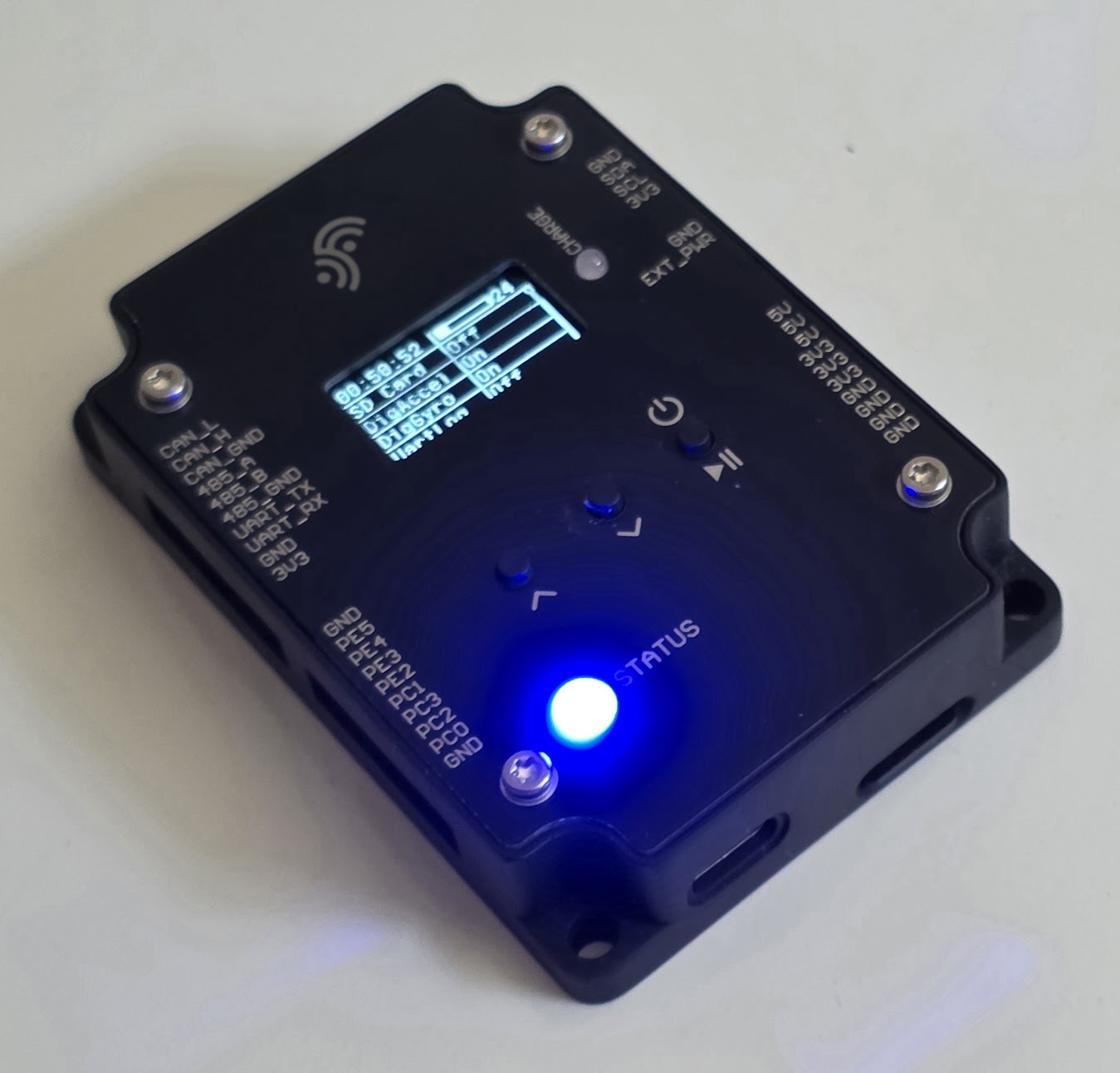
Reference design
A vibration logger, and the analysis that makes it useful
Hardware is half of a measurement product. The other half is turning a waveform into a number an engineer will act on. We build both, and you can try the analysis side right now.
The problem
A rolling-element bearing does not announce a fault at its fault frequency. An incipient spall produces a train of microscopic impacts that repeat at the ball-pass frequency — typically 3–12× shaft speed, so tens to a few hundred hertz — but each impact rings the housing at its structural resonances, usually 2–20 kHz.
Read the raw spectrum below 1 kHz and you see nothing until the fault is already advanced. The diagnosis needs envelope analysis: band-pass around the resonance, take the Hilbert envelope, transform that. The repetition rate then appears cleanly, with sidebands at shaft speed for an inner-race defect.
Which means the requirement is carrier bandwidth, not signal bandwidth. That single fact drives the entire front-end specification.
What that demands of the hardware
A general-purpose IMU tops out near 5–7 kHz with noise density in the hundreds of µg/√Hz — enough for overall vibration severity, marginal for early diagnosis. Parts built for the job reach 6–23 kHz of flat bandwidth at 25–75 µg/√Hz.
The mounting matters as much as the sensor. Above a few kilohertz the transfer path dominates: a stud mount holds to roughly 10 kHz, adhesive to 5 kHz, a magnet to 2 kHz. A sensor floating on a PCB inside a plastic box will report a resonance of its own housing and call it a bearing.
Sample-clock accuracy sets frequency accuracy directly — you are looking for a peak within a few percent of a computed ball-pass frequency, so the timebase is a specification, not an implementation detail.
The current prototype samples at 16.666 kS/s per axis, so the analysis reaches 8.33 kHz. That covers the lower and middle housing resonances where envelope demodulation is usually done, and not the highest — a deliberate ceiling we state rather than round up.
Drop in your own accelerometer CSV. It runs entirely in your browser — nothing is uploaded, and it works offline.
| Sensor | 3-axis MEMS, digital |
| Sustained sample rate | 16.666 kS/s per axis |
| Analysis bandwidth | DC – 8.33 kHz (Nyquist) |
| Measurement range | ±32 g |
| Controller | STM32 family |
| Storage | microSD card |
| Power | External DC; bench LiPo ≈ 1 h |
| Wired interfaces | CAN, RS-485, UART, I²C, GPIO |
| Wireless | In development |
| Enclosure | CNC-machined aluminium |
| Mounting | Screw mount, in development |
Measured on the prototype, not copied from a datasheet. The sensor is still under evaluation against alternatives, so the part is not published — the sampling and range figures above are what the current build sustains. The on-board battery covers bench sessions only; a deployed unit runs from external DC or a pack sized to the duty cycle.
What the analysis produces
Welch-averaged spectrum with selectable window and NFFT, spectrogram, and parabolic-interpolated peak picking. Condition indicators computed per capture: velocity RMS over 10–1000 Hz for ISO 20816 zone classification, high-band acceleration RMS, crest factor and kurtosis.
Trends matter more than absolute values, so the architecture sends roughly a hundred bytes of indicators per interval and keeps the raw waveform on the card for retrieval when an indicator moves. Three axes at 16.666 kS/s is about 100 kB/s, or 360 MB per hour — full-rate streaming over a narrowband link is not a thing. Burst capture with edge computation is.
The prototype is wired: CAN, RS-485, UART and I²C are brought out so a unit can join whatever bus the machine already has. The radio path is in development — which protocol makes sense depends on the site, and that is a question we would rather answer with you than in advance.
Reports export as A4 PDF carrying the record metadata, the analysis settings and the visible range — so a measurement can be reproduced from the report alone.
Where this applies
Same architecture, different mechanism
Rotating machinery
Bearing and gearbox condition monitoring, pump cavitation, fan imbalance and blade-pass, motor fault signatures, machine-tool chatter.
Structures
Bridges, masts, cranes and tower monitoring; construction vibration nuisance against DIN 4150-3; settlement and tilt.
Logistics and assets
Transport shock and drop recording to ISTA and ASTM profiles, tamper and impact detection, rolling-stock axle-box monitoring.
Human exposure
Whole-body vibration to ISO 2631 and hand-arm to ISO 5349 — a compliance purchase, with weighting filters defined by the standard.
All of these need the same three things: a precise front end, processing at the edge because the link is narrow, and industrial interfaces that fit what is already on the machine.
Capabilities
Electronics, firmware and mechanics under one contract
The alternative is an EE house, a mechanical shop and a firmware contractor — and you owning every interface between them. Breadth is the point, so here is where each discipline starts and stops.
Electronics
Mixed-signal design, low-noise analog front ends, power, EMC-aware layout. Multilayer boards with controlled impedance and fine-pitch BGA. Manufacturing packages as Gerber X2, ODB++ or IPC-2581, with a BOM carrying qualified alternates rather than a single-source risk.
Controlled-impedance stack-up — dielectric heights and trace geometry set together, not after layout.
Signal chain from sensor to link — anti-alias filtering and edge processing sized to the narrowest link in the system.
Connectivity and firmware
LoRaWAN, NB-IoT and LTE-M, 4G and 5G gateways, Wi-Fi and BLE, with antenna integration and matching measured rather than assumed. Pre-compliance scanning in-house; formal testing through an accredited lab.
On the firmware side: acquisition, edge DSP — FFT, envelope demodulation, condition indicators — telemetry over MQTT, and evaluation front-ends like the analyser above.
Mechanics
Enclosure and bracket CAD, thermal design, sealed and IP-rated integration, FDM and SLA prototypes, CNC machining. For sensing products the mechanical path is part of the measurement, not packaging around it — mount stiffness sets the usable bandwidth.
The current prototype uses a CNC-machined aluminium housing, and its screw mount is still in development. That ordering is deliberate: with an 8.33 kHz analysis ceiling, a magnetic mount at roughly 2 kHz would throw away most of the band the electronics can already resolve.
Sensor housing — a metal base coupling the PCB directly to the machine. Mount stiffness, not the sensor, sets the ceiling.
Front-end response verified on the bench against the design target, not taken from the datasheet.
Measurement and validation
Every design is characterised before it ships: front-end response and noise floor, power rails under load, thermal behaviour at temperature extremes, and link budget at range. You receive the test report with the numbers, including the ones that came out marginal.
How we work
What you receive, phase by phase
Phase 0 is deliberately small and self-contained. It ends with a fixed-price quote for phase 1, so you can stop after two weeks with a specification you own and no further obligation.
Fit
Where we help — and where we don't
A good fit
- Industrial measurement and retrofit sensing
- Products needing electronics, firmware and mechanics together
- Production volumes from 10 to 10 000 units per year
- EU design and manufacture requirements
- Projects where the measurement itself is the hard part
Not a fit
- High-volume consumer products competing on BOM cost
- Safety-critical certified development without a partner lab
- ASIC or custom silicon development
- Software-only or app-only projects
- Work where the design files cannot be handed over
Contact
Talk to the engineer who will do the work
What to send
A paragraph on what you are building, the environment it runs in, and your rough volume is enough to get a considered answer — usually within two working days.
Small senior team. You talk directly to the engineer doing the work, not an account manager.